Smart Home Tablet
For this project, I designed and built a custom smart home tablet powered by a Raspberry Pi. The device integrates a display, stereo speakers, a charging circuit, a boost converter, and a rechargeable battery, all housed in a custom-fabricated enclosure.
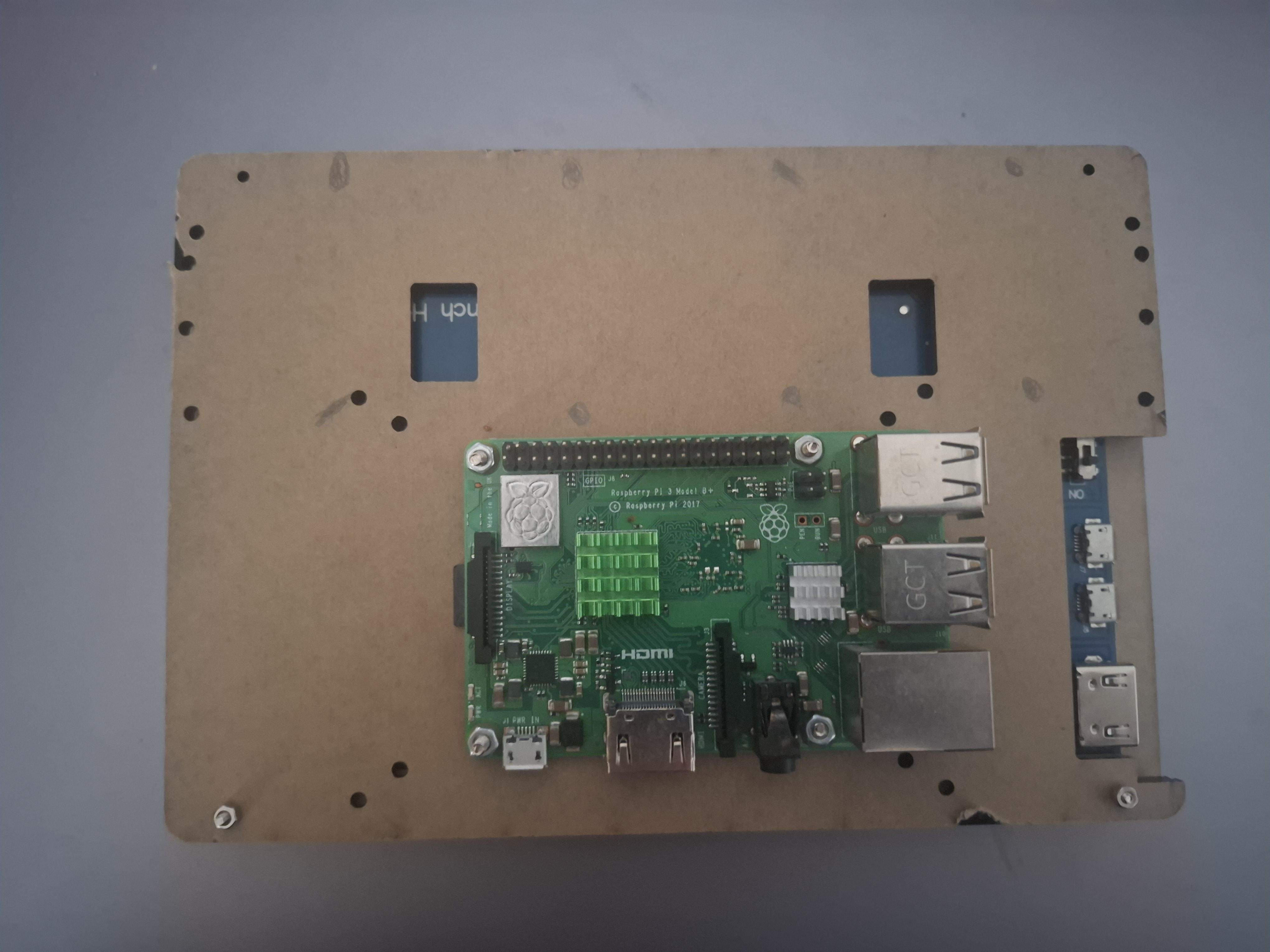
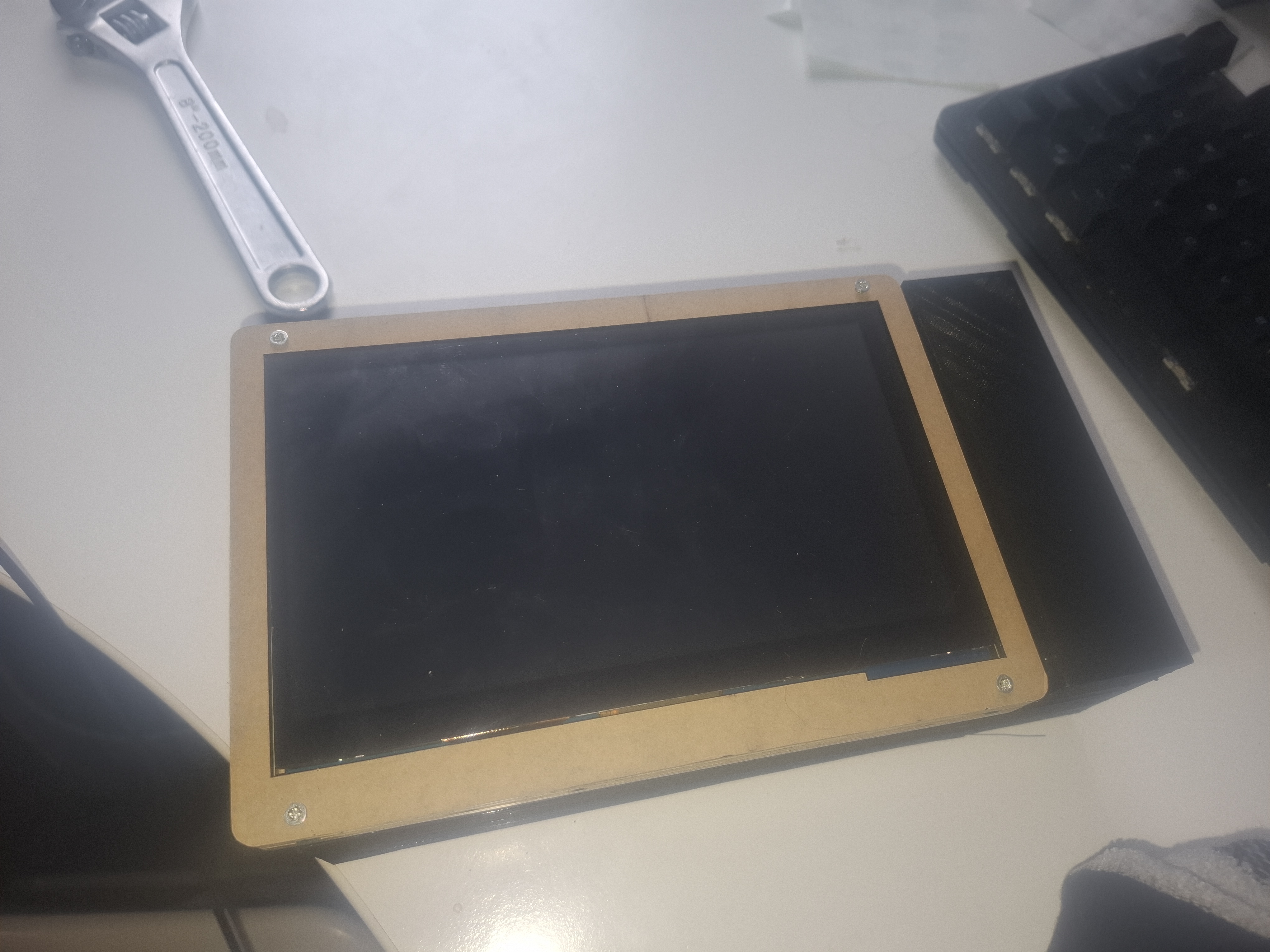
I began by laser-cutting a casing for the display, creating both front and back panels that securely wrapped around the screen. The design included precise mounting holes for the Raspberry Pi and proper ventilation, with a heatsink installed on the CPU to prevent overheating during operation. Care was taken to ensure the screw holes were in the same place for each of the laser cut layers of which there were four in total. The layers comprised of a back panel, a cutout frame and two display frames.
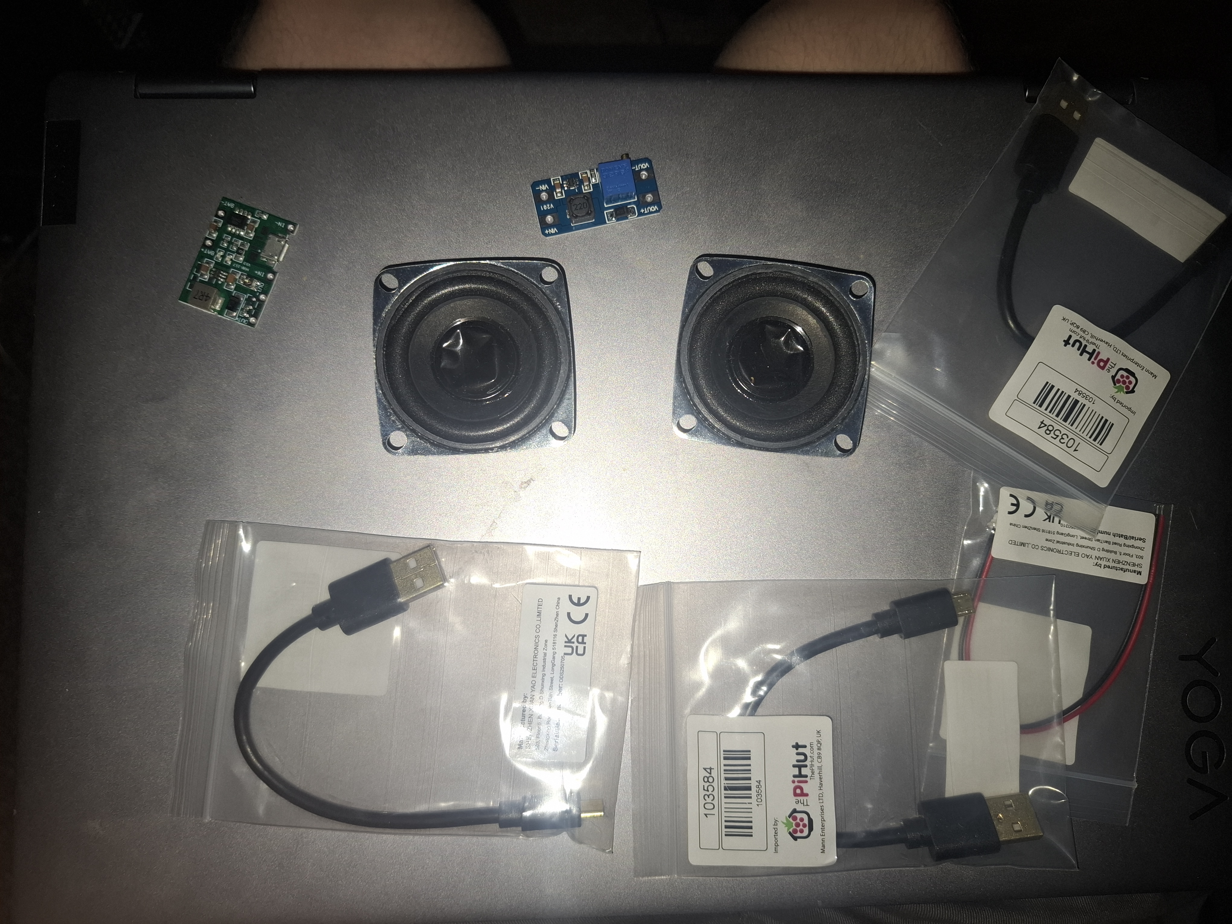
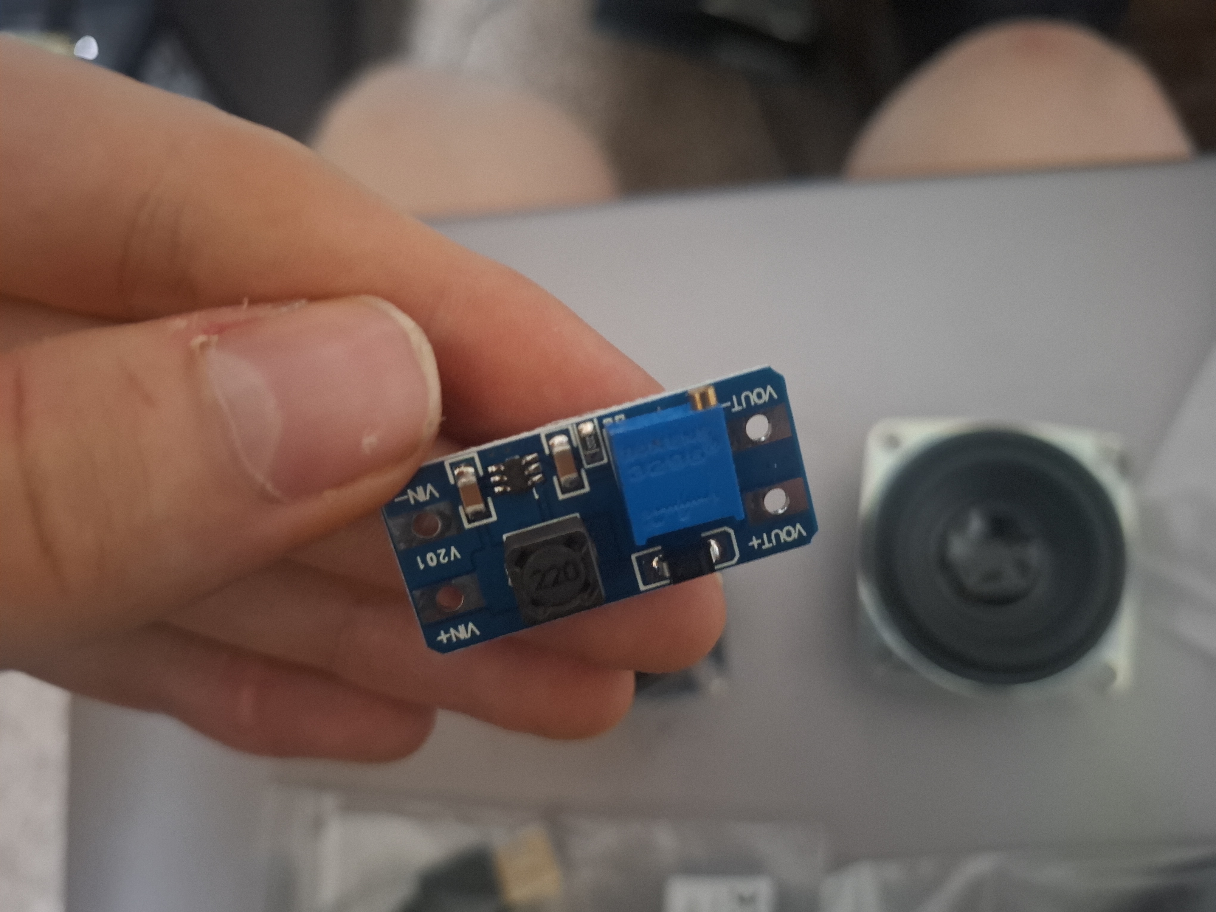
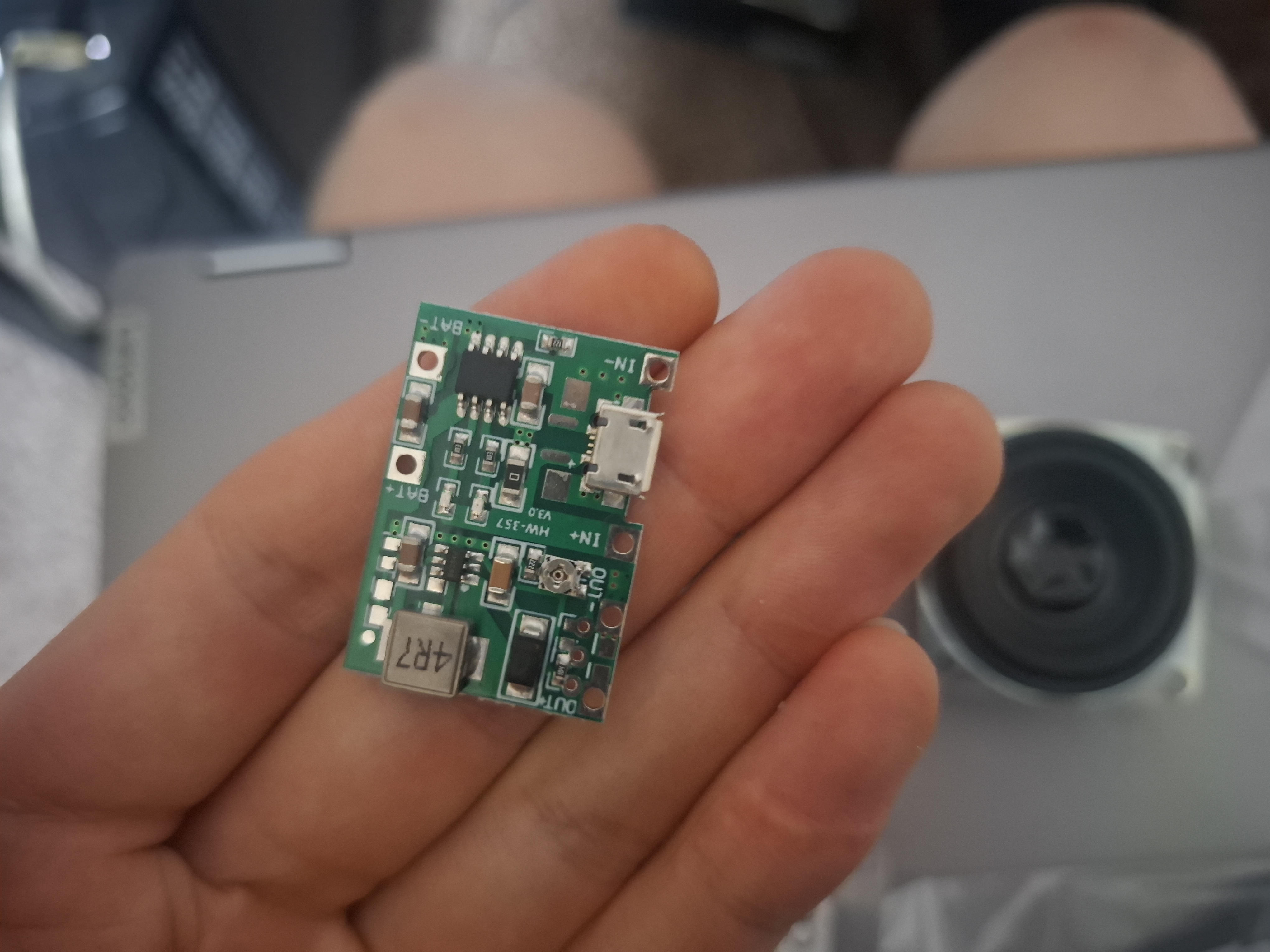
To power the device, I firstly tried using a 4000mah battery with a 3.7 V–4.2 V TP4056 charging circuit and an MT3608 adjustable boost converter to bring the circuit to 5V. These components allowed the battery to charge efficiently and provided stable power to the Raspberry Pi. This stage required soldering JST connectors and modifying micro-USB ports to work as pin inputs for the booster board. However, upon powering, the circuit was insufficient to power both the Raspberry Pi, the display and the speaker unit simultaneously which was an oversight on my part. So, to rectify this, an alternative solution in the form of a premade battery bank was used as I saw this to be the most effective option.
The speaker system was repurposed from a USB speaker which contained an internal amplifier with volume control. The potentiometer for volume control was removed and instead was replaced with protected copper wire as no hardware volume control was necessary.
The Raspberry Pi was originally configured to run Android using the Emteria installer. This provided a familiar touchscreen interface suitable for smart home device. However, this operating system proved to be problematic due to the limited performance of the Pi 3 model B. Raspbian was attempted next, however, although the operating system is touch enabled and an on-screen keyboard could be installed, I didn’t feel the OS was a good fit for a tablet due to its desktop layout and formatting. Therefore, a smart home operating system called LibreElec was chosen. This operating system proved to be a good fit for the smart home use-case.
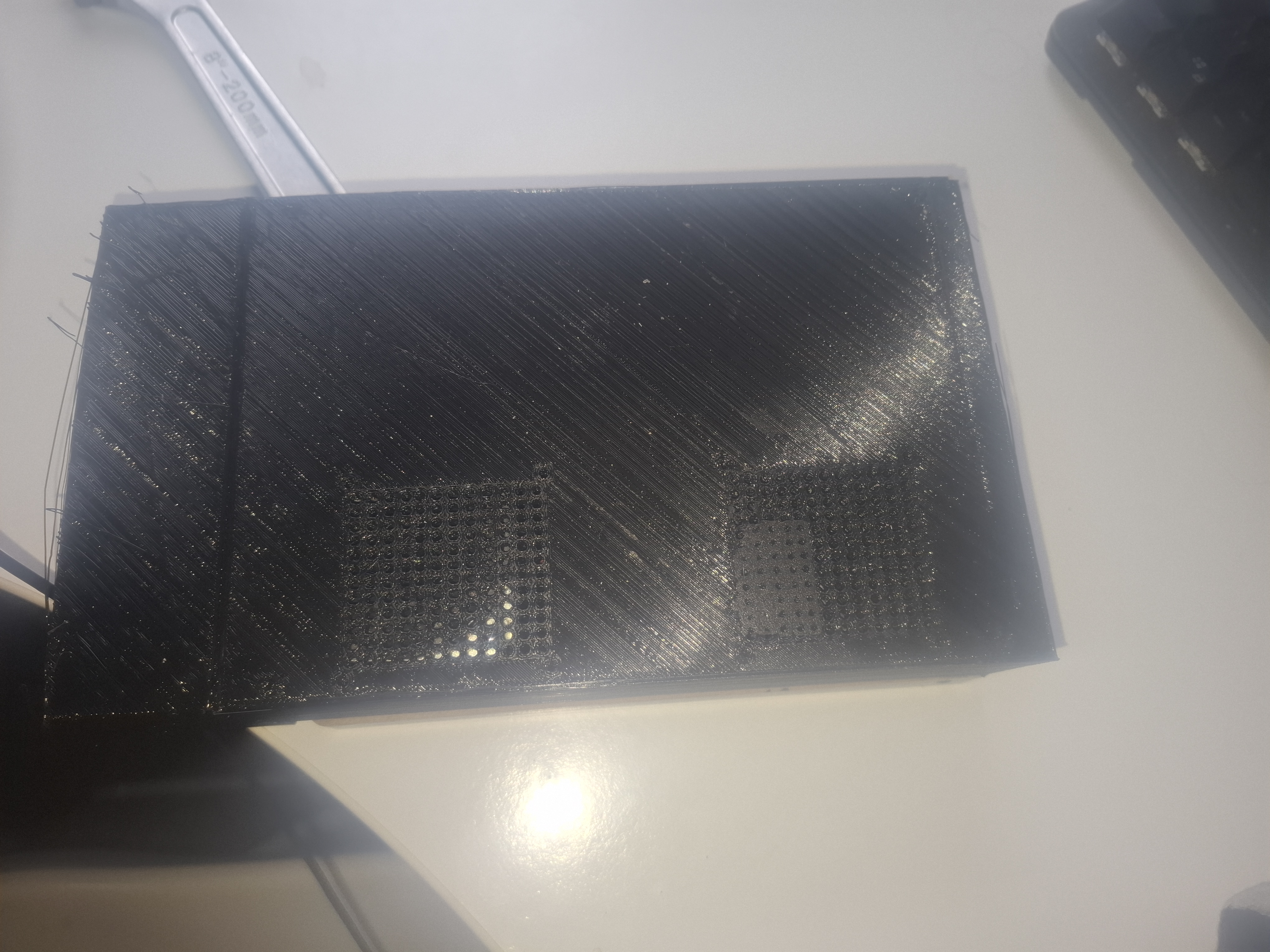
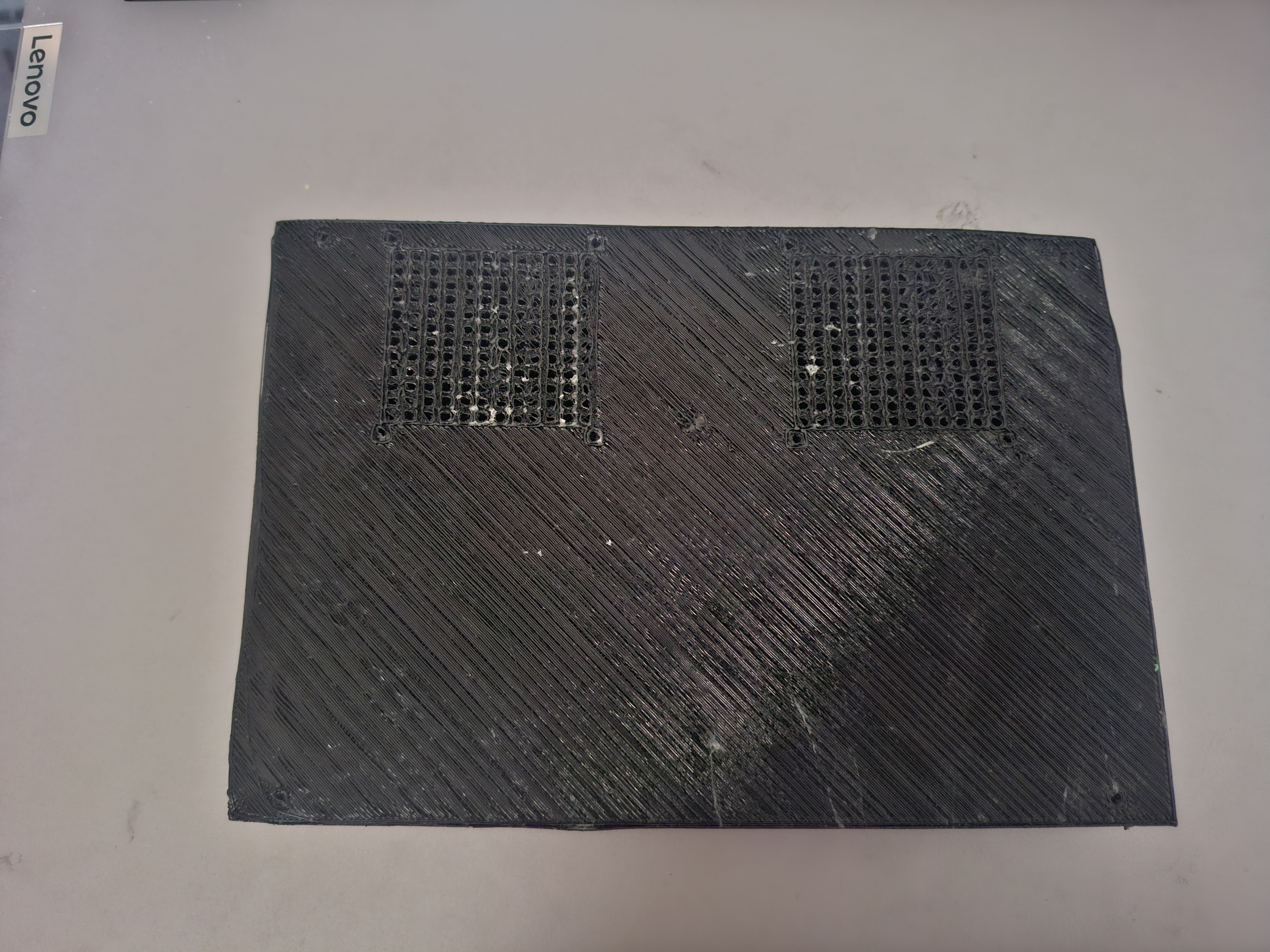
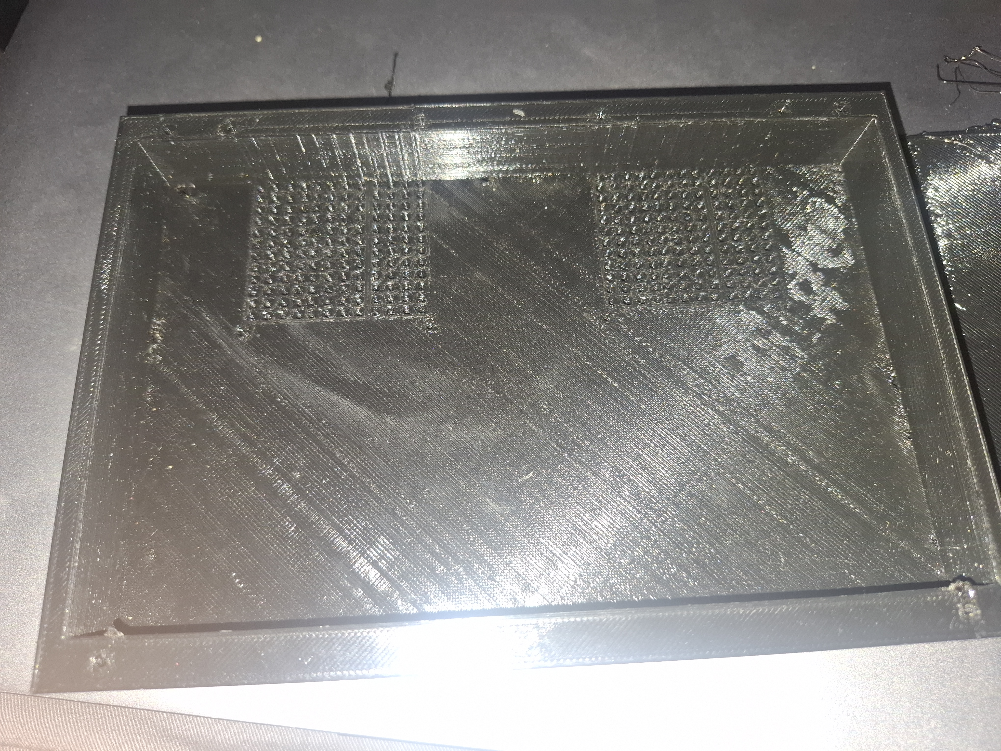
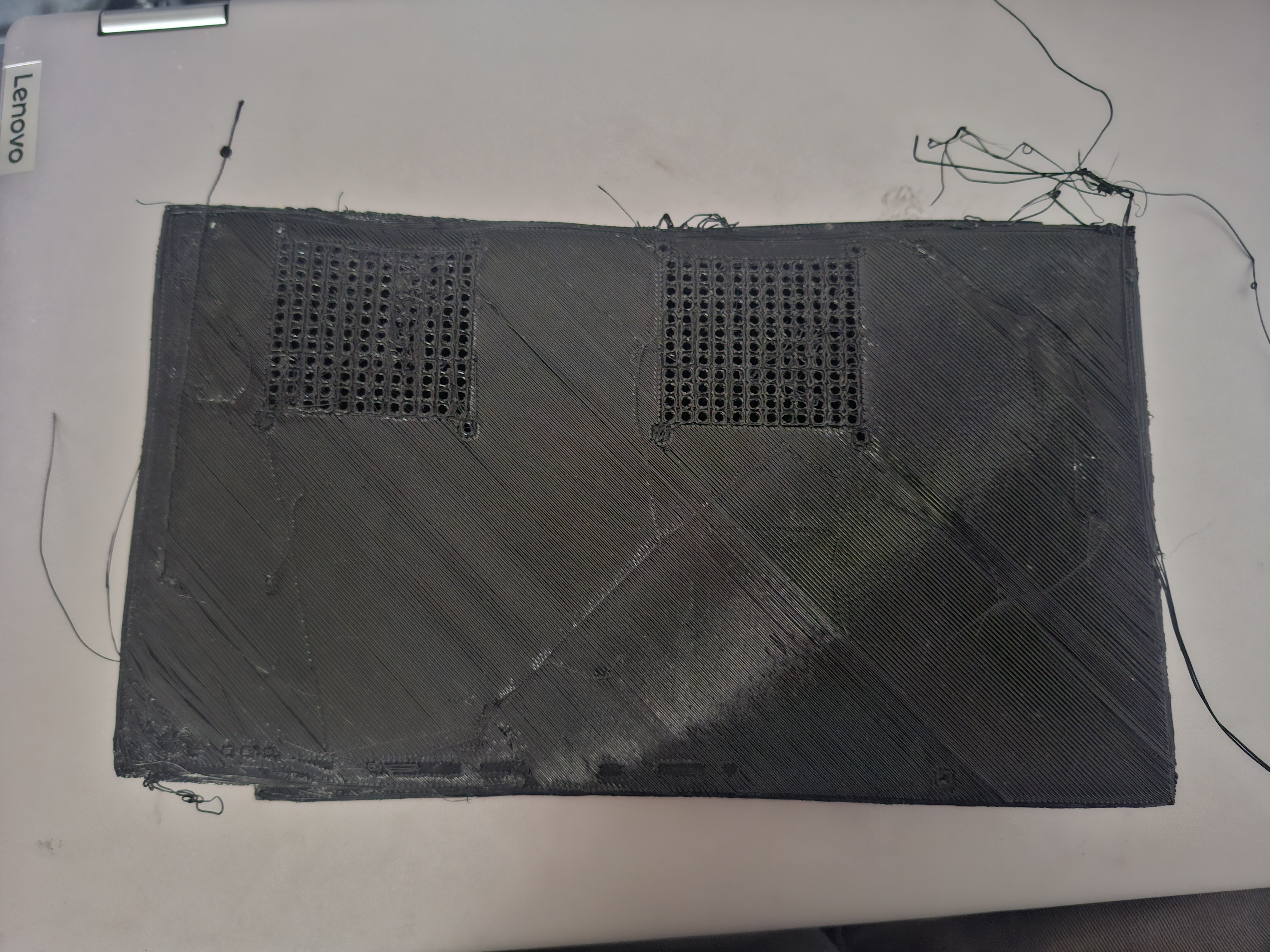
Finally, I designed and 3D-printed the back panel of the tablet, ensuring it included a charging port cutout, cable routing space, and speaker grills. Achieving a high-quality print required multiple troubleshooting steps and careful print tuning. This was one of the most time-consuming parts of the project. I had to ensure enough space would be left for all the components and their cabling and that the screw mounting holes were in the correct place. Finally, the plastic filament needed to have adequate adhesion to the print bed. This took a few attempts, and a few different methods were used to master it including different glues, bed levelling, print-bed temperature adjustments, nozzle temperature adjustments, print speed, in-fill percentges and fan speeds.
You can see some of the attempts of the 3d print in the images. At first, I didn’t leave enough tolerance for the cables on the right-hand side (if the screen is facing you) and so I had to print another model which allowed for this. I also had to ensure the right hand side of the 3d print was higher so it would line up correctly with the screen (see pictures for clarification). This required careful planning and measuring.
This project combined skills in CAD design, 3D printing, laser cutting, electronics assembly, and software configuration, resulting in a fully functional, portable smart home hub. This project taught me a lot about making prototypes for product development, the importance of planning and how to understand and deal with the pitfalls along the way to creating a finished design.